Jim_P_Pulfrew
XGE
- 931
- 0
- 16
Much appreciated, thanks!
Jimps
Jimps
The Bloodhound sooties did a little bit more than just fuel and defuel the missile.
Though lacking the turning bits of a normal jet engine, the Thor Ramjets on the Bloodhound did have an engine control system which was tested as part of the missile servicing. The Bloodhound Mk 2 carried about 52’ish gallons of Avtur in two bag tanks either side of the wing bay. As well as containing the biggest casting on the airframe which held the moving wing mounts, along with the actuators that moved the wings, at the centre of the bay was the fuel turbopump. This was driven by ram air from a pair of auxiliary air intakes between the ramjets and the mainbody (correct term for the fuselage of a missile). As well as supplying air to the fuel pump, these intakes also supplied air to a hydraulics turbopump which powered the certain mechanical parts of the missile and also supplied air to pressurise the fuel tanks. The fuel pump had two impellers, the front one was driven by the air from the top intake, and feed fuel from the front tank to the upper ramjet. The rear one was feed from the lower intake and fed fuel from the rear tank to the lower ramjet. Each impeller had its speed controlled by a fuel flow sensor that opened a spill valve to dump air before it got to the impeller turbine. Fuel entered the ramjet via a Fuel Air Ratio Control (FARC) system mounted in the island assembly at the front of the engine (behind the shock cone on the engine intake). The FARC measured the altitude of the missile via a pitot mounted on front of the engine shock cone, and controlled the amount of fuel feed to the fuel injectors (Lower altitude, more fuel and vice versa).
There were two sets of fuel injectors on the Thor engine. A single injector fed a pilot combuster can at the rear of the island assembly which kept the engine alight and the fuel fed to it was controlled by the FARC to give a fixed cruise thrust level. Forward of this pilot can was a separate secondary ring of 12 injectors which had their fuel flow controlled by FARC system, along with a device called the Thrust Control Unit (TCU) mounted in the missile mainbody behind the Hydraulics Turbopump. The TCU had two main functions. First it controlled the missile’s speed, below the missile’s cruising speed of Mach 2.7, it allowed the engines to run at full power by allowing maximum fuel flow to the secondary ring of 12 injectors. Once the missile reached its cruising speed and height, the TCU chopped the amount of fuel to the secondary ring and throttled the engine back. (Max power of the two engines was around 10,000/11,000 pounds which for a missile weight with the boosters gone was a thrust to weight ratio of about 4 to 1.)
The other thing the TCU did was cut the amount of fuel going into the engine when the missile did a hard manoeuvre. Mounted on the nose was a cone like device called the incidence switch, which operated if the missile’s pitch or yaw attitude to the direction of flight went over an angle of about 5 degrees. One of the problems that was found with the Bloodhound Mk 1 was that shockwaves in the engine intake which helped provide the compression of the incoming air, moved within the intake when the missile manoeuvred. This lead to a loss of compression (being that there was no turning compressor) and then to an incorrect fuel air ratio, which in a lot of cases led to a flameout due to a rich fuel air mixture. The TCU and incidence switch on the Mark 2 overcame the problem. Each engine had three cartridges fitted to it. One was a gas charge which blew the weather covers off (they forgot to fit them on Bloodhound 1), while the other two were flares which lit the pilot combustor which burnt for about 10 seconds. All three were fired 2 seconds before the boost motors were ignited.
On a missile major the sootie had to remove, refit and test these parts, some guys hated it, some loved it. In a lot of ways it was an easy job. I knew some TG1 guys who were at Raynham for ages.
As for the acronyms:
MOTE – Missile Overall Test Equipment. A large rig that supplied Electrical, Air and Hydraulic oil to a missile undergoing ground servicing, it also simulated the Ground radar used to guide the missile and the reflected echo from the target.
WREBUS – Weapon Research Establishment Break Up System. A Weapons range saftey device designed at the Weapon Research Establishment at Woomera in Australia during the 1950’s. The WREBUS was fitted to a number of British guided weapons and rockets when fired on trial ranges. Basically it was a radio receiver, arming system and a small charge of explosive mounted on the missile airframe (on Bloodhound Mk 2 it was located within the Warhead bay of the missile, just in front of the forward fuel tank). Normally trial missiles were fired sans warhead, the bomb being replaced with an instrument package, which recorded data of a number of missile voltages, signals, fuel flow, Hydraulics pressures and a number of other bits of data on what the missile was doing and transmitted them to the ground. When the WREBUS was armed on launch it would do nothing as long as it received a signal from the ground. Lose the signal due to the range safety officer activating the system (by chopping the signal) or WREBUS receiver failure. The system would blown the side out of the warhead bay and aerodynamic forces would do the rest. Other systems were also tacked on to a trials missile like doppler transponders and alike to allow precise tracking and recording of the missile’s flight path.

I did Bloodhounds on 242 SQN at RAF Marham in 1960, from there I went to Scampton to work on Blue Steel. Both situations illustrated what the COLD meant in the COLD WAR!!cup of corrrfeee
Since reading this thread, I've been racking my old brain to identify the control system from the ADRS station to the bloodhound site. Link 5 is lurking at the forefront of my mind for some reason. I've checked all my various tech folios and it wasn't listed there. I'm sure that there was a feed from the Elliot 920b computer (a whole 20K of memory installed) at SLEWC. Any info as it's driving me up the wall now?
Got any Colour Photos of a Mark 1 with 'Live' Boosts on them or any photos from 242 at the time. I could really use them. Worked on the Mk 2 myself.


Been following the conversation for a while. Hope you don't mind me butting in.....
This any use to you?
Also got:
and with dummy boosts (I think)
 DT_Xtremez_42:DT_Xtremez_42:
Here's one getting a lift from a Belvequeer....
Hope these are of interest...
Doc
DT_Xtremez_30:DT_Xtremez_30:Fascinating stuff, that, and thanks.
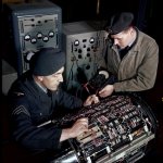
I was interested to be able to identify a Marconi Sig Gen on top of the MOTE; brought back a few memories.
What sort of Bang did these things have?. I mean, how did the missle actually take down an aircraft? Fly up alongside and detonate (with maybe a slack handful of nails for the A/c intakes), or fly straight up the tailpipe and contact ?
And what happened to the installation that was at Cosford Museum ?.
DT_Xtremez_34: he heMainjafad, your knowledge of the Bloodhood is amazing, if you had the choice between making love to a beautiful woman or stroking the shaft-like mainbody of a mk2 Bloodhound missile fitted with "live boosts", what would you do ?
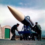
I have also found this which I am sure is a drill Bloodhound Mark 1, sans boosts, sans fins. Are the engines under covers?
I am trying to find others in the collection but its taking some time.
Oh I should add - From Imperial War Museum Collection: No. RAF-T 562
Doc
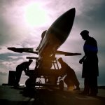
Mainjafad - thanks for the info. I don't have anything else within that particular series which will give any further detail, but I do have these:
A slightly dramatic silhouette and what appears to be some of her insides - though this last one could be anything.....
Again from IWM collections.....
Left IWM RAF-T 560
Right IWM RAF-T 561
Doc
i had the pleasue of being on the fire section at west raynham 88-90,i was told that,some hounds hd been taken to the range to be test fired and the very first one misfired with a bit of a pop?
DT_Xtremez_09: